Key Points
- Radar absorbing material (RAM) reduces radar cross-section by converting incident RF energy into heat through dielectric loss, magnetic loss, or both. Every absorber design trades bandwidth against thickness under the Rozanov bound.
- Magnetic absorbers loaded with carbonyl iron or ferrite get thin at low frequency and pay for it in areal density and temperature sensitivity. Permeability falls as the filler approaches its Curie point.
- The topcoat over the absorber is part of the electrical stack, not a finish applied after the fact. Its permittivity, loss tangent, and film build tolerance move the reflectivity null whether or not the RF model accounted for them.
- Polyurethane topcoats degrade above 177°C / 350°F and silicones crack under vibration, so low-observable surfaces in nacelle, exhaust, and engine bay zones get stripped and recoated on a maintenance clock instead of a mission clock.
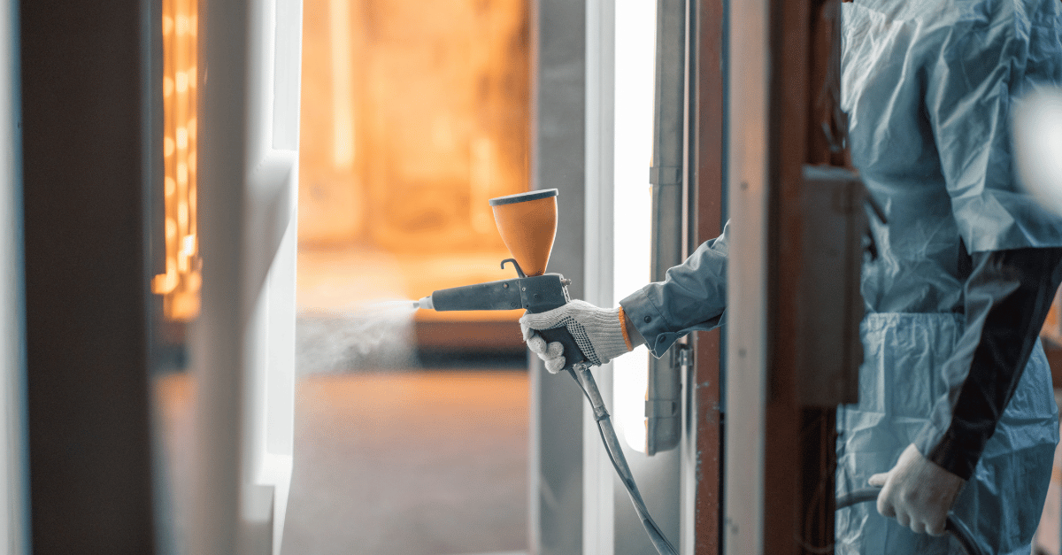
- GREOS ENDURE FKM coating holds 250°C / 480°F longterm with elastomeric flexibility and flight line fluid resistance, and sprays with standard equipment.
Two Loss Mechanisms Do All the Work
Radar absorbing material reduces radar cross-section by forcing an incident electromagnetic wave to dissipate as heat inside the layer, through impedance matching, resonance, and dielectric or magnetic loss, rather than reflecting back to the receiver. Two loss mechanisms carry that work, and the choice between them drives everything downstream: thickness, weight, band coverage, and temperature ceiling.
Dielectric absorbers rely on the imaginary part of complex permittivity. Conductive fillers dispersed in a binder create conduction paths and polarization relaxation that dissipate field energy, and the loss tangent tracks filler loading and particle morphology. Push the loading high enough to get useful loss and the layer stops behaving like a coating. It behaves like a filled slab: stiff, dense, and prone to cracking at the substrate interface.
Magnetic absorbers work on complex permeability instead. Natural ferromagnetic resonance and domain wall motion give you absorption at electrical thicknesses far below a quarter wavelength, which is why every thin low-frequency absorber on a real platform is magnetically loaded. Snoek's limit caps the product of permeability and resonance frequency, so ferrites dominate below X-band and lose ground above it.
Coatings are one branch of RCS reduction, not the whole discipline. Radar absorbing structures embed loss into the composite airframe itself, geometric shaping redirects the return away from the threat radar, and RAM coatings do the job those two methods can't: adding absorption to an existing surface without redesigning the structure underneath it.
The filler families engineers actually specify come down to a short list:
- Carbon blacks, graphite, and conductive fibers: dielectric loss through conduction; light, cheap, percolation-sensitive.
- Carbonyl iron powder: high permeability, high density, the default for thin broadband magnetic layers.
- Spinel and hexagonal ferrites: tuned resonance for specific bands, with Curie temperatures that vary sharply by composition and can sit inside the operating range of an exhaust-washed panel.
Layer Design Sets the Band. Thickness Sets the Limit.
An absorber is an impedance matching problem with a loss term. You're trying to present something close to free-space impedance at the outer surface, dissipate the energy inside, and keep whatever reflects off the ground plane from returning in phase. Hit that and you get 90% absorption at minus 10 dB reflectivity, or 99% at minus 20 dB.
The classic architectures each solve it differently, and each one fails differently.
| Architecture | Primary loss | Band behavior | Thickness driver | Where it breaks |
|---|---|---|---|---|
| Salisbury screen | Resistive sheet near 377 Ω/sq | Narrow null at design frequency | Quarter-wave spacer | Thick at S-band; null shifts with spacer permittivity |
| Jaumann multilayer | Graded resistive sheets | Multi-octave | Quarter wave per sheet | Areal density and build complexity |
| Dallenbach layer | Bulk dielectric or magnetic loss | Narrow to moderate | Filler loading and film build | High loading kills flexibility |
| Magnetic loaded layer | Complex permeability | Strong below X-band | Permeability, not wavelength | Weight; permeability drops near Curie temperature |
| Circuit analog sheet | Patterned resistive elements | Broad and tunable | Element geometry plus spacer | Tolerance-sensitive registration and etch control |
Every row depends on the same fragile assumption: a physical spacing and a material constant staying exactly where the model put them. Change the dielectric constant of any layer in the stack, or shift its thickness by a few tens of microns, and the null walks off the design frequency.
Essential Background Reading:
- FVMQ Explained: Material Properties, Limits, and What Engineers Reach for Next: Foundational rundown of fluorosilicone chemistry limits, the pillar reference for this cluster.
- Fluorosilicone Coating: Temperature Limits, Failure Modes, and When to Specify FKM Instead: Baseline failure temperatures and mechanisms for silicone topcoats before comparing alternatives.
- FVMQ O-Ring Guide: Temperature Range, Skydrol Compatibility, and Compression Set Specification: Reference data on fluid compatibility and compression set specification terminology used throughout this piece.
The Topcoat Is the Part That Fails Qualification
The absorber usually passes. It gets designed by RF engineers, measured in a chamber, and iterated until the reflectivity curve looks right. Then a topcoat goes over it, and the program discovers that the outermost 50 to 150 microns of the stack are the part nobody budgeted risk against.
The topcoat sits in the incident field before the wave ever reaches the absorber. Its permittivity adds to the electrical stack, and film build tolerance adds phase error. Surface roughness governs specular return and traveling wave behavior at grazing incidence. Metallic flake pigments are disqualifying, which is why LO finishes run complex inorganic color pigments rather than conventional aerospace metallics.
Then the environment gets involved. A nacelle panel, thrust reverser, or engine bay door on a low-observable platform routinely exceeds 177°C / 350°F, which is where polyurethane chemistry starts breaking down. The film chalks, loses thickness, and changes its dielectric properties while it does it. Silicone survives more heat and then cracks under vibration and thermal cycling, and cracks scatter. Once the topcoat delaminates, the absorber underneath takes direct fuel, hydraulic fluid, and de-icer exposure it was never formulated to resist.
That's how a qualified RF design turns into a depot problem. The stack was never electrically wrong. The surface layer just couldn't hold its properties through the thermal and chemical environment the mission actually delivers.
Related Content:
- Fluorosilicone FVMQ vs. FKM: Temperature, Fuel Resistance, and When Each Fails: Side-by-side comparison of where FVMQ holds up and where FKM chemistry takes over.
- Fluorosilicone Coatings for Aerospace: Temperature Limits, Failure Modes, and FKM Alternatives: Broader look at fluorosilicone limitations across aerospace hot zones beyond the RAM stack.
- Fluorosilicone Release Coatings: Where They Work (and Where FKM Takes Over): Context on where fluorosilicone release chemistry remains viable and where FKM chemistry replaces it.
Why No One Fixed the Topcoat
Fluoroelastomer chemistry solved the thermal and chemical durability problem decades ago. FKM and FFKM seals have held pressure against fuel and hydraulic fluid at temperatures that destroy every organic topcoat in production. The physics was never the obstacle.
The supply chain was. Large chemical suppliers move fluoroelastomer volume into seals, O-rings, and gaskets, where compression molding is established and margins are stable. Reformulating that chemistry into a sprayable topcoat means new solvent systems, new rheology work, and new application qualification, all for coating volumes that are a rounding error next to sealing products. Incumbent aerospace coating suppliers have fully amortized polyurethane lines already qualified to legacy airframer specs, and no commercial reason to obsolete them. Airframers write new specs against what's already qualified. The loop closes and stays closed.
GREOS exists to close that gap: a sprayable fluoroelastomer topcoat for hot zones, built because no one in the existing supply chain had an economic reason to build it.
Next Steps:
- GREOS ENDURE: FKM Fluoroelastomer Coating for Commercial Aviation: Full specification sheet for the coating referenced throughout this article.
- FVMQ Material Properties Explained: Datasheet Values vs. Real Hot-Zone Performance: Deeper dive into the gap between datasheet permittivity values and real thermal-cycling performance.
- Radar-Absorbing Materials on Hot Structures: Why Standard Topcoats Fail and What Replaces Them: Next-level read on hot-structure RAM applications and topcoat replacement criteria.
What an LO Topcoat Has to Survive
The requirement set for a surface layer over radar absorbing material is narrow and unforgiving. It has to stay dielectrically stable, stay attached through thermal cycling and vibration, resist JP-8 and phosphate ester hydraulic fluid, hold film build tolerance across a large panel, and finish smooth enough that surface roughness never becomes an RF variable.
| Topcoat chemistry | Longterm thermal rating | Flight line fluid resistance | Behavior under vibration | Consequence for the stack |
|---|---|---|---|---|
| Polyurethane | ≤ 177°C / 350°F | Poor against fuels and Skydrol | Flexible until thermal aging embrittles it | Chalking and film loss detune the surface layer |
| Silicone | ≤ 315°C / 600°F | Poor against fuels and solvents | Brittle; cracks and delaminates | Cracks scatter; delamination exposes the absorber |
| Ceramic barrier | 538°C+ / 1000°F+ | Good | Zero vibration tolerance | Weight penalty and thermal shock cracking |
| GREOS ENDURE FKM coating | 250°C / 480°F | Excellent vs fuels, hydraulic fluids, de-icers | Elastomeric across the full thermal cycle | Film stays intact; the electrical stack stays as designed |
See It In Action:
- Radar Absorbent Material in Aerospace: Performance Specs, Failure Modes, and Topcoat Compatibility: Applied performance specs and topcoat compatibility data for aerospace RAM programs.
- Radar Absorbing Materials: Why Topcoat Failure Destroys Your Signature Budget: Program-level breakdown of how topcoat failure translates into signature budget overruns.
Frequently Asked Questions
These are the questions that come up most often when engineers evaluate RAM coatings and the surface layer over them.
What is radar absorbing material made of? Radar absorbing material typically consists of a binder loaded with conductive fillers like carbon black and graphite for dielectric loss, or magnetic fillers like carbonyl iron powder and ferrites for magnetic loss. The filler choice and loading level set the loss tangent, the achievable band, and the layer's mechanical behavior.
Does radar absorbing material make an aircraft invisible to radar? No. Radar absorbing material reduces radar cross-section within a designed frequency band and angle of incidence; it doesn't eliminate the return across all frequencies. A platform coated in RAM remains detectable outside its design band or from angles the absorber wasn't tuned for.
What's the difference between radar absorbing material and radar absorbing structure? Radar absorbing material is a coating or applied layer added to an existing surface, while radar absorbing structure embeds loss directly into the composite airframe during layup. RAM offers retrofit flexibility; RAS offers permanence without the added mass of a surface layer.
Why do stealth coatings need to be reapplied or maintained? Legacy topcoat chemistries like polyurethane degrade above 177°C / 350°F and silicones crack under vibration and thermal cycling, so the outer layer over the absorber loses adhesion, film thickness, and dielectric stability over time. That degradation detunes the electrical stack, forcing recoat on a maintenance schedule rather than an as-needed basis.
Specify the Surface Layer Before the Stack Locks
Most LO programs treat the topcoat as a finishing decision made after the RF design freezes. That sequencing is what puts qualification risk at the end of the schedule, where it costs the most to fix.
GREOS ENDURE FKM coating carries a 250°C / 480°F longterm rating, holds elastomeric flexibility through thermal cycling, resists flight line fluids, and sprays with standard equipment using a CARB-exempt solvent system. No new application process to qualify. For platforms operating above that ceiling, GREOS VANGUARD FKM+ and GREOS APEX FFKM extend the architecture to 325°C / 600°F and 350°C / 660°F longterm.
No More Compromise in Hot Zones.
Request Technical Datasheet or Contact Application Engineer to review substrate compatibility, film build tolerance, and dielectric characterization requirements for your stack.
Performance characteristics and temperature ratings are based on internal laboratory testing. Actual results may vary by application, substrate, and operating conditions. Customers should conduct their own testing to confirm suitability for their specific use cases.