Key Points
- Radar absorbing materials perform to their design point only when the layers above them hold their dielectric properties and their thickness. The topcoat sits inside the electromagnetic stack and behaves like part of it.
- Polyurethane topcoats degrade above 177°C / 350°F, silicones delaminate under vibration, and each failure changes surface impedance and boundary geometry in ways that show up in the RCS budget.
- Every hot-zone repaint adds thickness, feathered edges, and a new interface to a stack that was tuned at build. Repaint frequency is therefore a signature variable.
- Qualify the topcoat against the same cycling, adhesion, and fluid standards you apply to the absorber: ASTM D412, ASTM D4541, ASTM D573, and RTCA DO-160G.
- GREOS ENDURE FKM coating holds elastomeric flexibility and fluid resistance to 250°C / 480°F longterm, which keeps the outer layer of the stack dimensionally and dielectrically stable through the thermal cycle.
What Radar Absorbing Materials Do, and Where the Public Literature Stops
Radar absorbing materials reduce radar cross-section by absorbing incident electromagnetic energy and converting it to heat, using impedance matching at the surface and resonance or dielectric and magnetic loss inside the material. That mechanism is well documented. It's also where most published coverage of radar absorbing materials stops.
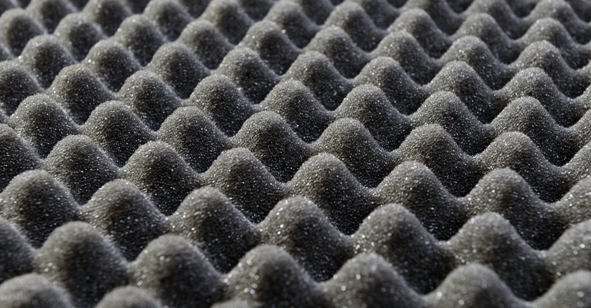
Material classes are established science at this point. Magnetic absorbers load permeability with ferrites, iron, or cobalt-nickel alloys. Dielectric and conductive absorbers load permittivity with carbon black, carbon fiber, carbon nanotubes, graphene, or metal flake. Form factor ranges from foam and sheet stock to sprayable coatings and structural composites known as radar absorbing structure (RAS). Each carries different weight, frequency coverage (commonly 1 to 40 GHz), and installation tradeoffs against a coating-based approach.
None of that changes once the part leaves the lab and gets flown. What changes is the surface stack sitting on top of it, and that's the layer the academic and patent literature doesn't touch.
Your Topcoat Is an Electromagnetic Layer
Absorber design assumes a known stack. Whether the layer is a Dallenbach-type lossy dielectric, a magnetic loading over a ground plane, or a multilayer graded-impedance construction, the tuning math takes the complex permittivity, permeability, and thickness of everything above the absorber as fixed inputs. The topcoat is one of those inputs.
Engineers on low-observable programs tend to treat the topcoat as a coatings-engineering deliverable and the absorber as an RF deliverable. Those are the same deliverable.
A topcoat with a different loss tangent than the one modeled shifts the resonant null. A topcoat that builds heavier on a compound curve than on a flat panel moves it again, and not uniformly across the airframe. The absorber did not change. The answer changed anyway.
Where the Stack Loses Signature Performance
Four zones in a typical low-observable coating stack carry RCS consequences, and only one of them is the absorber itself. The table below maps each layer to the property that matters electromagnetically and the mechanism that degrades it in service.
| Stack layer | RCS-relevant property | In-service degradation mechanism |
|---|---|---|
| Primer / surface treatment | Adhesion to substrate, film uniformity | Corrosion undercut, blistering at the substrate interface |
| Absorber (RAM) layer | Complex permittivity, permeability, thickness | Moisture absorption, filler migration, thermal aging |
| Topcoat | Dielectric constant, loss tangent, thickness uniformity, surface continuity | Thermal cracking, chalking, embrittlement, fluid swelling |
| Edges, fasteners, sealant transitions | Boundary geometry, continuity of the lossy surface | Feathered repaint edges, sealant shrinkage, coating lift at fastener heads |
Three of the four rows describe mechanical failures that produce electromagnetic outcomes. That's the argument.
Essential Background Reading:
- FVMQ Explained: Material Properties, Limits, and What Engineers Reach for Next: Baseline chemistry primer on fluorosilicone elastomer properties and where engineers turn once its limits are reached.
- Radar Absorbent Material in Aerospace: Performance Specs, Failure Modes, and Topcoat Compatibility: Foundational reference on RAM performance specifications and how topcoat selection affects absorber compatibility.
- Fluorosilicone Coating: Temperature Limits, Failure Modes, and When to Specify FKM Instead: Covers the temperature ceilings and failure mechanisms that define when fluorosilicone stops being the right call.
- FVMQ Material Properties Explained: Datasheet Values vs. Real Hot-Zone Performance: Explains the gap between published FVMQ datasheet values and how the material actually behaves in service.
Thermal Cycling Drives the Degradation in Hot Zones
Nacelles, thrust reverser assemblies, engine bay panels, APU compartments, and exhaust washed surfaces routinely exceed 177°C / 350°F, past the point where polyurethane topcoats hold together. Add the cycle count. A coating that survives one soak at temperature is a different material after 500 cycles between cold soak and peak.
Cracking is the failure everyone photographs. Delamination is the one that determines whether the stack survives, because a lifted topcoat introduces an air gap with a dielectric constant near 1.0 directly above a layer designed to see a specific dielectric above it. You built an unintended impedance discontinuity, distributed unevenly across the panel.
Chemistry determines which failure you get and when.
| Topcoat chemistry | Longterm thermal rating | Dominant failure mode | Signature consequence |
|---|---|---|---|
| Polyurethane | ≤ 177°C / 350°F | Thermal degradation, embrittlement, chalking | Surface roughening, crack networks, frequent repaint cycles |
| Silicone | ≤ 315°C / 600°F | Brittleness, adhesion loss under vibration, poor fuel and Skydrol resistance | Delamination gaps above the absorber, edge lift |
| Ceramic barrier | 538°C+ / 1000°F+ | Rigidity, thermal shock cracking, weight penalty | Crack-induced scattering, mass penalty against payload margin |
| FKM fluoroelastomer | 250°C / 480°F | Retains elongation and adhesion through the cycle | Stable film, no cycling-driven discontinuities |
Related Content:
- Fluorosilicone FVMQ vs. FKM: Temperature, Fuel Resistance, and When Each Fails: Side-by-side comparison of temperature ratings and fuel resistance between fluorosilicone and FKM chemistry.
- Radar Absorbing Material: Why the Topcoat Determines Whether the Stack Survives: Detailed look at how topcoat integrity, not the absorber itself, decides whether a low-observable stack holds up.
- Fluorosilicone Release Coatings: Where They Work (and Where FKM Takes Over): Maps the application window for fluorosilicone release coatings against the point where FKM becomes the better spec.
Rework Is a Signature Event
Hot-zone repaint intervals set the cadence of stack disturbance. A topcoat that needs stripping and recoating every couple of depot visits means the stack above your absorber gets rebuilt repeatedly by technicians working to a film-thickness spec, not to an RF tuning spec.
Each rework adds three things the original model did not include: a feathered transition at the repair boundary, a new adhesive interface, and cumulative thickness where masked edges overlap. None of that shows up on a dry film thickness gauge reading that passes.
Extending repaint intervals is therefore an RF strategy. GREOS ENDURE extends hot-zone repaint intervals 3 to 5 times over polyurethane alternatives, which removes disturbance cycles from the stack over the life of the airframe.
Why This Gap Has Stayed Open
Fluoroelastomer chemistry is not new. The carbon-fluorine bond has delivered thermal stability and chemical resistance in high-performance seals for decades, and every materials engineer reading this already knows that. The question is why nobody made it sprayable for an airframe.
The answer is economics, not physics. Large chemical suppliers formulate for volume, and aerospace hot-zone topcoats are a low-volume, high-qualification-burden market compared with architectural and automotive coatings. Incumbent aerospace coatings houses hold qualified positions under existing airframer specifications, and a new chemistry threatens those positions without expanding the addressable market. Airframers write specifications against what is already qualified, which locks the incumbent chemistry in place and gives nobody a reason to fund the reformulation work.
So the compromise persisted. Engineers on low-observable programs kept trading thermal capability against flexibility against fluid resistance, and the signature budget absorbed the difference.
GREOS exists to close that gap. The company formulates FKM and FFKM fluoroelastomer chemistry as sprayable aerospace topcoats, filling the supply hole that incumbents had no commercial reason to fill.
Next Steps:
- GREOS ENDURE: FKM Fluoroelastomer Coating for Commercial Aviation: Full technical profile of the FKM topcoat referenced throughout this article, including thermal range and fluid resistance data.
- FVMQ O-Ring Guide: Temperature Range, Skydrol Compatibility, and Compression Set Specification: Specification reference for FVMQ seal components, including Skydrol compatibility and compression set limits.
- Fluorosilicone Coatings for Aerospace: Temperature Limits, Failure Modes, and FKM Alternatives: Implementation-level detail on fluorosilicone temperature ceilings and the FKM alternatives available for hot zones.
How to Audit Your Stack as a Signature System
Run this sequence before the next design review. It takes the coating stack out of the finishes package and puts it in the RF package, where it belongs.
- Pull the dielectric assumptions: extract the permittivity, loss tangent, and nominal thickness the absorber model assumed for every layer above the RAM, including primer and topcoat.
- Measure what you actually applied: compare modeled thickness against as-built dry film thickness across flat panels, compound curves, and fastener zones separately. Curvature build is where the variance lives.
- Map thermal zones against topcoat capability: overlay the thermal survey on the coated surface map and flag every region where sustained temperature exceeds the topcoat's longterm rating.
- Inspect cycled hardware, not coupons: look for edge lift, crack initiation at fasteners, and chalking on returned components. Coupon data will not show you the fastener-head geometry.
- Count rework cycles per zone: treat each stripped and recoated region as a stack rebuild, and assign it a tolerance stack-up penalty in the signature budget.
See It In Action:
- Radar-Absorbing Materials on Hot Structures: Why Standard Topcoats Fail and What Replaces Them: Applied look at how standard topcoats fail on hot structures carrying RAM and what replaces them in service.
- Radar Absorbing Materials: Why Topcoat Failure Destroys Your Signature Budget: Companion analysis quantifying how topcoat failure translates directly into signature budget overruns.
What to Require of a Hot-Zone Topcoat on an LO Platform
Write the topcoat requirement against the absorber's operating environment rather than the general airframe finish specification. The following belongs in that requirement.
- Longterm thermal rating with margin: rated above peak sustained zone temperature, not at it, and verified under ASTM D573 heat aging.
- Elongation retention after cycling: measured per ASTM D412 before and after thermal exposure, because a topcoat that loses elongation loses adhesion next.
- Adhesion pull-off after thermal and fluid exposure: ASTM D4541, tested post-conditioning rather than on fresh panels.
- Fluid compatibility across the operating range: jet fuels, phosphate ester hydraulic fluids, and de-icing agents per ASTM D471.
- Environmental qualification: RTCA DO-160G vibration and temperature-altitude sections, with the coated article in the loop.
- Dielectric characterization at operating frequency: permittivity and loss tangent supplied by the coating vendor.
That last bullet is the one most programs skip, and it is the one that makes the rest of the stack model honest.
Frequently Asked Questions
What are radar absorbing materials made of? Radar absorbing materials use either magnetic loading (ferrites, iron, or cobalt-nickel alloys) or dielectric and conductive loading (carbon black, carbon fiber, carbon nanotubes, graphene, or metal flake) suspended in a binder or matrix. The choice of filler determines whether the material primarily absorbs through permeability loss or permittivity loss.
How do radar absorbing materials work? Radar absorbing materials reduce radar cross-section by matching the impedance of the material to free space at the surface, minimizing reflection, and then converting the transmitted energy into heat through resonance or dielectric and magnetic loss inside the layer. Designers tune thickness, filler loading, and frequency range together to hit a specific absorption band.
What's the difference between radar absorbing material and radar absorbing structure? Radar absorbing material (RAM) is typically a coating, sheet, or foam applied to or bonded onto an existing surface. Radar absorbing structure (RAS) integrates the absorbing function directly into a load-bearing composite part. RAM offers retrofit flexibility and lower weight penalty per unit area; RAS eliminates a separate applied layer but locks the absorption profile into the structural design.
Can radar absorbing material coatings be sprayed on like a standard topcoat? Some RAM systems spray on, but most commercially available paste-on RAM materials are difficult to apply uniformly and don't reliably deliver high-performance, multi-frequency absorption once installed. The topcoat above the RAM layer sprays with standard equipment when a formulator gets the chemistry right, and that topcoat's dielectric stability matters as much as the absorber's.
What causes radar absorbing material coatings to fail in service? The absorber layer itself degrades through moisture absorption, filler migration, and thermal aging, but a large share of in-service signature loss traces to the topcoat above it: thermal cracking, chalking, embrittlement, and delamination that change surface impedance and boundary geometry. A failure in either layer changes the RCS answer the stack was designed to produce.
Specify the Outer Layer Against the Signature Budget
Signature performance degrades from the outside in. The absorber can hold its properties perfectly while a cracked polyurethane topcoat or a delaminated silicone above it rewrites the surface impedance your model depended on. GREOS ENDURE FKM coating survives 250°C / 480°F longterm with elastomeric flexibility intact, resists flight line fluids, applies with standard spray equipment using a CARB-exempt solvent system, and holds a smooth, color-matched finish through the thermal cycle. For platforms operating above that band, GREOS VANGUARD (325°C / 600°F longterm) and GREOS APEX (350°C / 660°F longterm) extend the same elastomeric behavior into fighter, hypersonic, and directed-energy environments.
Performance characteristics and temperature ratings reflect internal laboratory testing. Actual results vary by application, substrate, and operating conditions, and programs should conduct their own qualification testing to confirm suitability. Discussion of program-specific signature requirements should follow appropriate ITAR handling.
No More Compromise in Hot Zones.
Request Technical Datasheet for GREOS ENDURE, or Contact Application Engineer to review your stack configuration and thermal zone map against the FKM platform.